![]() Estimating Edge’s team of experienced construction professionals and software engineers have developed the industry’s smartest takeoff and estimating software solutions for competitive estimates.
Estimating Edge’s team of experienced construction professionals and software engineers have developed the industry’s smartest takeoff and estimating software solutions for competitive estimates.
Don’t just estimate faster. Estimate better.®
- /
- /
- /
Visuals for Concrete Conditions
Condition Properties General Information
Each condition is designed to handle different parts of the project. One condition can be used for multiple parts.
For example, the Wall Footing condition is used for a wall footing, thickened edge, or thickened slab. Each would be a separate condition modified as needed.
Auto Feed
We have designed The EDGE for minimum user input and maximum output. This is done by feeding measurements you input in one field to automatically fill in other fields. (See the separate document for examples of auto feed in the various conditions.) When you are in the parent field, the child fields on the same screen turn red italics. When your cursor is not on the parent field, the child field is black with no italics.
Disabled Fields
There are several disabled fields. These are fields where you see information, but the field is not editable. These fields have a gray background instead of the standard clear or white background. This can be for the following reasons:
- The field is turned off – (i.e., it will not be calculated for that condition.)
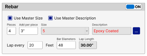
- Child field from a master (parent) field – Rebar size is one example. If you check Use Master Size, the information comes from the master size, and you cannot change it directly in the field. However, if you uncheck Use Master Size, then the gray goes away, and you can edit the field directly.
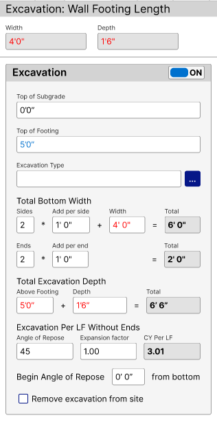
- Auto calculation – When a field is a result of other fields, it is often non-editable. Examples of this are the Lap Length for rebar or the CY Per LF for Excavation in a Wall Footing.
- Auto calculation but still editable – Not all auto calculation fields are non-editable. Some calculate a result, but its background is not gray. You can still edit the field. One example is the rebar Length field in the Column Count stirrups. This is auto calculated from the column dimensions but can be changed.
Note: It is often better to not change the auto-calculation and instead adjust in the Add per Piece field. This way you can set parameters and have minimum input when dimensions change.
Examples
Below are examples of what we discussed in the previous section.
Auto-Feed
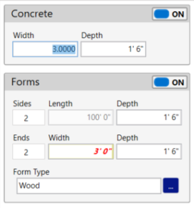
In the figure below, the cursor is on the Concrete Width field. The child field in the Forms Width is in red italics. Once the cursor moves off the parent field, the child field font will be standard and black.
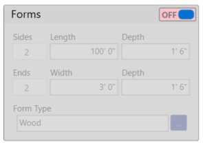
Field is Turned Off
Since the field is turned off, no formwork will calculate.
Child Field from a Master (Parent) Field
If the cursor is on the Use Master Size field, the child field will be red italics. Once the cursor moves off the parent field, the child field font will be standard and black.
Auto Calculation
In the figure below, the CY Per LF field and the Total fields are results of the other fields.
Auto Calculation but Still Editable
In the figure below, the column dimensions are used to calculate length of the stirrups (L x W x2). However, you can still override it.
Hint: It is often better to not change the auto-calculation and instead adjust in the Add per Piece field. This way you can set parameters and have minimum input when dimensions change.
Additional Measurement Fields
Each condition has one primary measurement. Either Area, Length, or Count. However, within each condition, there may be other fields that can be measured differently than the primary measurement.
To do this, while on the drawing screen, the program will default to the primary measure mode. As an example, let’s say you measured a wall 20’ long. You want a depression in the wall to go the entire wall length. However, you want a protrusion to go only part of the wall length. You would set the Depression to “Total LF,” but the Protrusion to “Measure LF.” If you only had one depression and one protrusion, the setup would look like this:
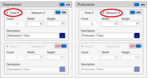
While out at the drawing screen, after measuring the wall length, you click the separate icon for Protrusion and measure that length.
Additional Measurements
Below are the additional measurements available for the various conditions.
Wall Footing Length
- “General” tab – Embeds – Count (instead of on-centers)
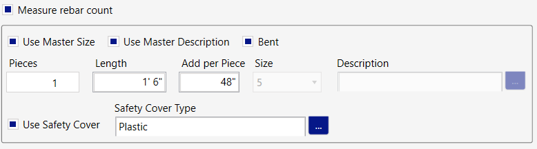
- “Rebar” tab – Rebar Centers/Vertical Bars – Measure Rebar Count
When checked, this allows a separate count for rebar.
Slab on Grade Area
- “General” tab – Measure Form Length (instead of perimeter)
- “General” tab – Plate Dowels – (Must Measure Length) – Since plate dowels do not go around the entire perimeter, this allows measuring a line along the centers where they go.
- “Rebar” tab – Rebar Centers at Perimeter – Measure Length (instead of perimeter). This comes in handy for adding rebar along part of the slab perimeter based on centers. This can be used for either vertical bars or horizontal rebar in the slab.
Elevated Slab Area
- “General” tab – Measure Form Length (instead of perimeter)
- “Rebar” tab – Rebar Centers at Perimeter – Measure Length (instead of perimeter).
Beam Length
- “General” tab – Embeds – Measure Count (instead of on centers)
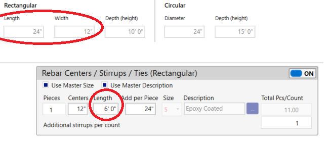
- “Rebar” tab – Rebar Centers/Stirrups/Ties – Measure different rebar centers (this is an additional length measurement. This is how it works. Let’s say you had a beam 50’ long. The stirrup centers on most of the beam are 12” on center. However, in 10’ of the beam, the stirrups centers are 6.” After setting the condition properties and measuring the 50’ beam, you click the separate Rebar Centers icon and measure the other 10’. The program will calculate the following stirrup count.
50-10=40LF / 12” = 40 stirrups, plus 10LF/6” = 20 stirrups. Total stirrups 40+20=60 stirrups. See the screenshot below for setup.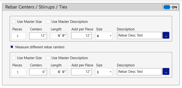
- “Rebar” tab – Rebar Centers/Vertical Bars – Measure rebar count. Allows you to count the rebar location instead of using centers.
Wall Length
- “General” tab – Depression – Measure LF (instead of Total LF)
- “General” tab – Protrusion – Measure LF (instead of Total LF)
- “Rebar” tab – Rebar Centers – Vertical – Measure rebar count. Allows you to count the rebar location instead of using centers.
Stair Count
- “General” tab – Concrete and Forms – Riser LF, Side Stringer LF, Mid Landing Area. In this condition, you have the option to measure various parts of the stairway or manually enter them. If you choose to measure any parts, the icon for that part will appear on the drawing screen.
- “Rebar” tab – Rebar Centers/Vertical Bars – Measure rebar count. Allows individually measuring each rebar location rather than on centers.
Stair Pan Count
- “General” tab – Concrete – Riser LF, Side Stringer LF, Bottom Landing Area, Mid Landing Area, and Top Landing Area. Similar to the stair count condition. You have the option to measure various parts of the stairway or manually enter them. If you choose to measure any parts, the icon for that part will appear on the drawing screen.
Conditions with No Additional Measurements
- Column Footing Count
- Column Count
- Common Area
- Common Length
- Common Count
Additional Information
Centers field
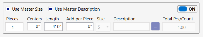
In most cases, if you enter zero in the Centers field, it will use the Pieces field as the result.
Example: Here is a Cross Bars input screen for a 4’x4’ column footing. Notice the Centers is 12”, so with Pieces set to 1, the Total Pcs/Count is 4.
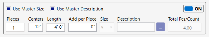
However, if Centers is zero, then Total Pcs/Count equals Pieces, which is 1.
Beam Form Properties
For an 8” wide x 24” beam, the form properties would typically look something like this:
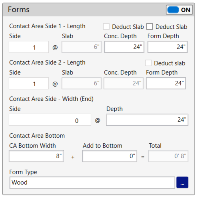
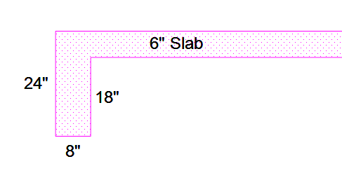
However, if the beam is on the perimeter of the slab, the engineer may include the slab thickness in the beam dimension and still call it an 8” x 24” beam. This detail might look like the diagram below.
We have designed the beam form properties to account for this. If you wanted to form the outside as 24” and the inside as 18” and you did not want the slab concrete to be included in the beam concrete, the properties would look like this:
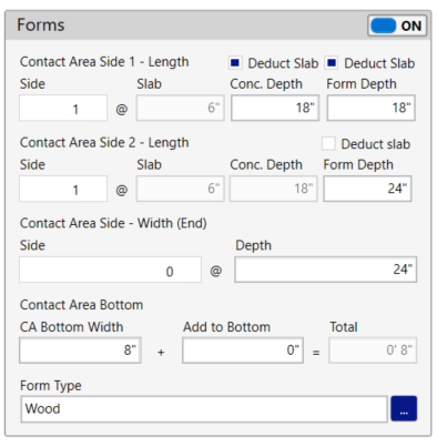
Note that the “Deduct Slab Conc Depth” applies to the entire beam but the “Deduct Slab Form Depth” can apply to one or both sides.
Condition Illustrations
Below are illustrations to help identify the various conditions.
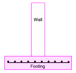
Wall Footing
Thickened Edge (done with Wall Footing Condition)
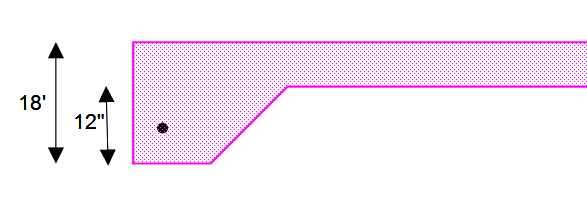
Thickened Slab (Done with Wall Footing Condition)

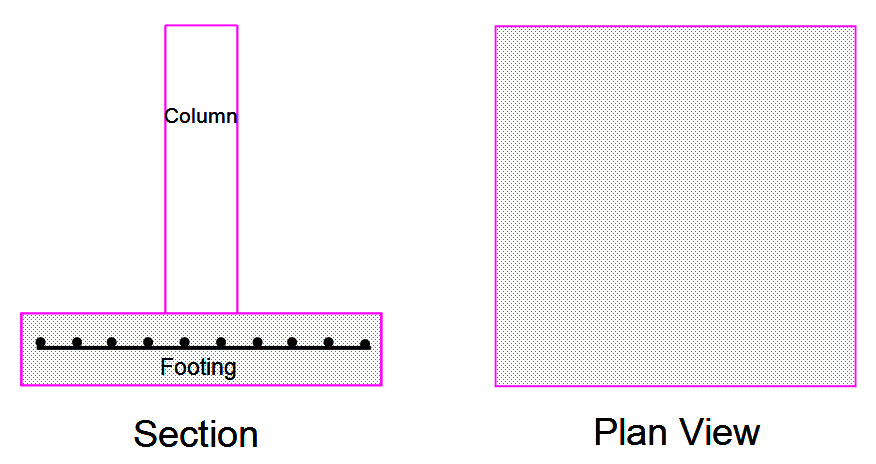
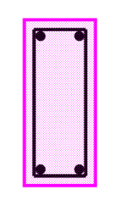
Column Footing
Beam
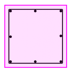
Column
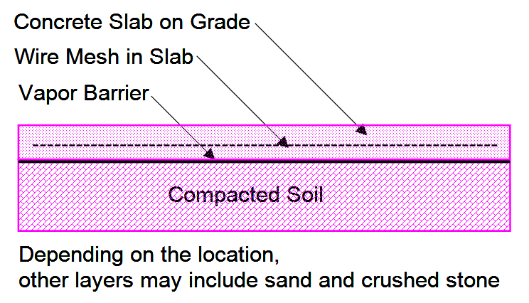
Slab on Grade
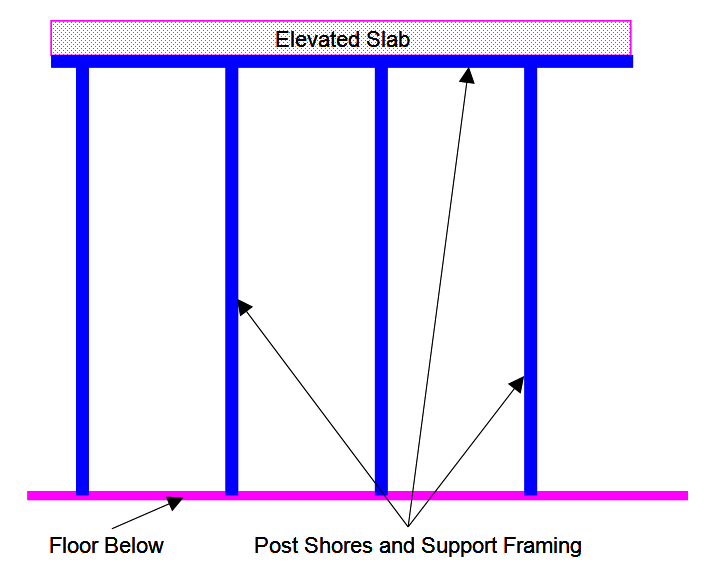
Elevated Slab
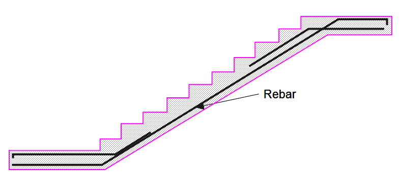
Stair
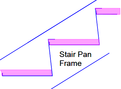
Stair Pan
A metal structure that has treads and landings filled with poured in place concrete. (There is no formwork required for pan stairs.)
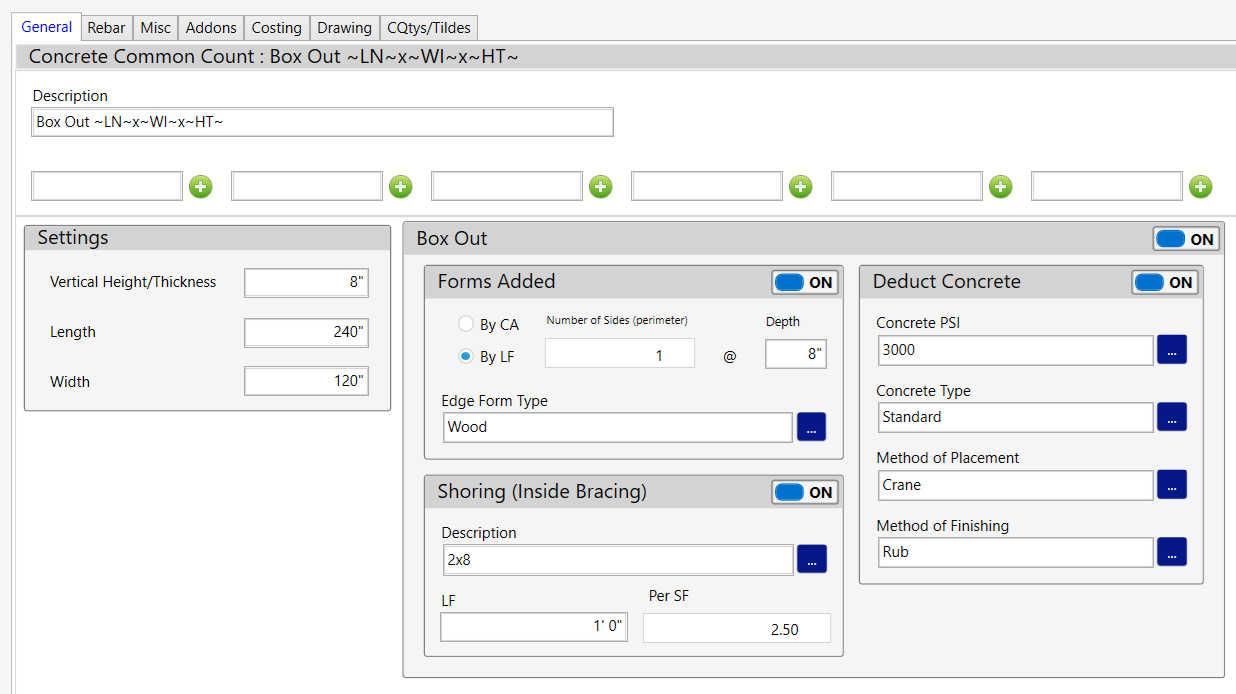
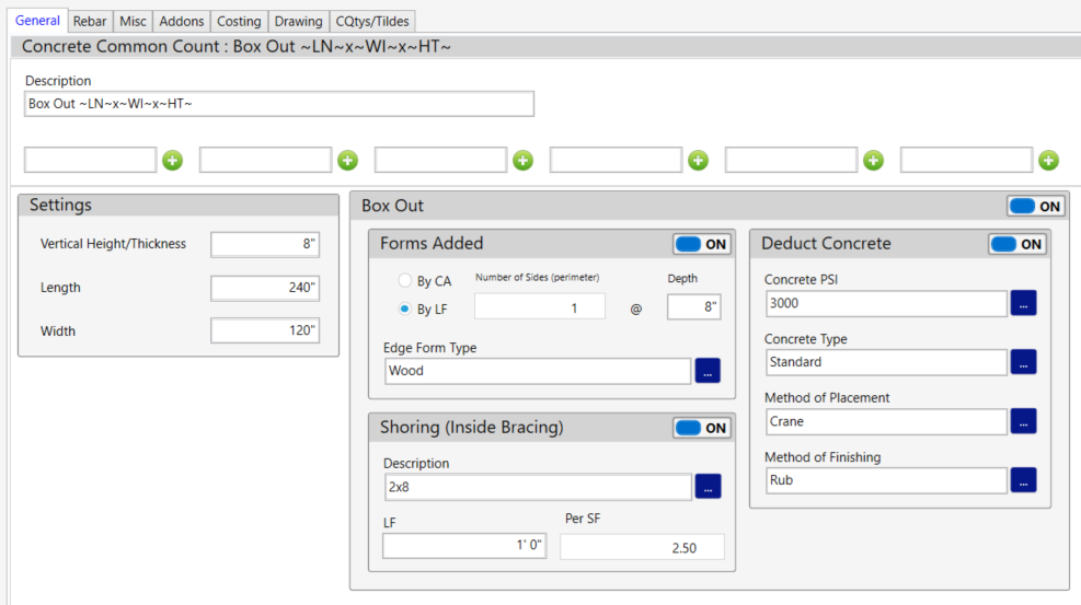
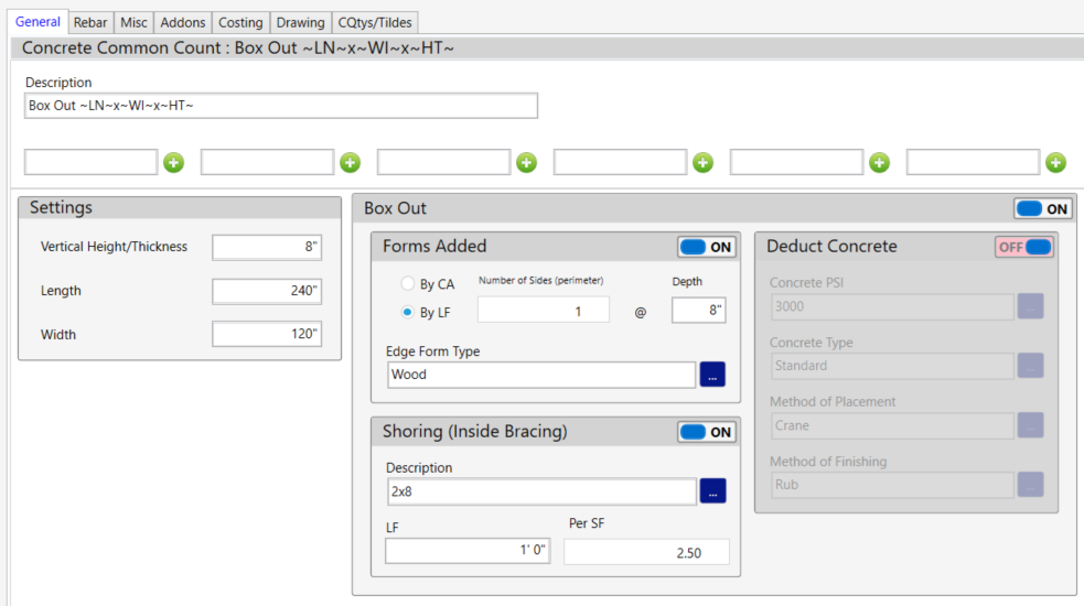
Box Out (in the Common Count Condition)
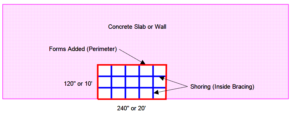
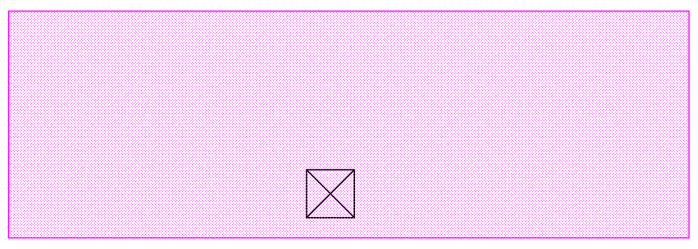
The illustration below shows an area that needs to be boxed out. In a wall, this might be for a door or window. In a slab, it might be a plumbing opening. (The perimeter and Bracing lines are for illustration only. The condition only shows a count.)
To set this up in our Box Out group (from the Common Count condition), it would look like this:
As mentioned in the drawing above, the perimeter and bracing lines are for illustration only. In the actual estimate, the same box out appears as a count as shown below.
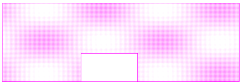
The above figure shows the box out as a count. If the Deduct Concrete portion is turned on, the concrete for the box out will be deducted and the condition would look like the figure below.
However, what if you had already deducted the boxed-out area when you measured the condition? The area drawing might look like this:
In this case, you would not want to deduct the concrete but would want to estimate the shoring needed to form the box out. Then the condition would look like this:
The Common Count condition may also be used for other counts that are not related to box-outs.